Arduino Multifunction Shield
|
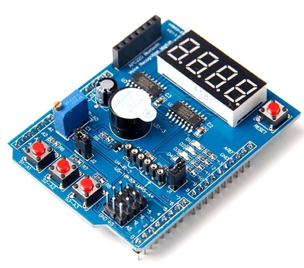
You might have seen one of these inexpensive add-on boards on Amazon or eBay and wondered what it was and how to program it. Well, I hope this section will give you a good idea of this board's capabilities and how to use it in your next project.
First, let's look at the installed capability: 1) An installed reset button to reset the attached Arduino.
2) 3 user defined pushbuttons (on analog inputs pins A1, A2, A3). 3) A potentiometer. This allows you to input a varying voltage to the Arduino (connected to analog input pin A0). 4) A gated buzzer. This is not driven directly from an Arduino pin but controlled by a transistor that is connected to Arduino digital pin D3. 5) A 4 digit 7-segment LED display that is driven through shift registers to select the digit and segments of that digit to be illuminated. 6) 4 board mounted LEDs (digital pins D10, D11, D12, D13). |
|
If you search the internet, you will find an Arduino library for this shield. The library is good, but creates an object that incorporates all of the possible board add on features and this makes it use a lot of resources. If you are just looking at some simple projects that require switches, leds, and a buzzer, you may not need all of that. This guide is not intended to replace the use of the library, but give the user a way to easily access the board features. Let's look at how to get started:
Let's define the board to make it easier to program
One of the convenient features of programming in Arduino is that you can define names to represent the Arduino pins. As you program, it is easy to remember that BUZZER is the pin that the buzzer is connected to. We will use a name for each of the features so we can make our code easier to read and write. Here is how we do that:
#define LED_1 13 // LED pins
#define LED_2 12
#define LED_3 11
#define LED_4 10
#define BUZZER 3 // The speaker enable
#define POTENTIOMETER A0 // The analog input for the potentiometer
#define BUTTON_1 A1 // The input pushbuttons
#define BUTTON_2 A2
#define BUTTON_3 A3
#define DISP_LATCH 4 // The 3 pins that control the display
#define DISP_CLK 7
#define DISP_DATA 8
If you insert these #define statements in the beginning of your Arduino code, you will now be able to refer to the features by their name instead of their pin number.
The next thing you usually want to do is set up the pinMode for each of these features. If you are a veteran Arduino programmer, you will have noticed that most libraries will do this for pins the library is going to use. However, it is good practice to ensure the pins are setup tto your liking. In your setup() procedure you would want the following pinMode() commands:
First, set the LED pins as outputs:
pinMode(LED_1, OUTPUT);
pinMode(LED_2, OUTPUT);
pinMode(LED_3, OUTPUT);
pinMode(LED_4, OUTPUT);
Write this pins high so they will turn off the LEDs:
digitalWrite(LED_1, HIGH);
digitalWrite(LED_2, HIGH);
digitalWrite(LED_3, HIGH);
digitalWrite(LED_4, HIGH);
Next, set the pushbuttons as inputs (there are pullup resistors on the board so there is no need for the internal pullups).
pinMode(BUTTON_1, INPUT);
pinMode(BUTTON_2, INPUT);
pinMode(BUTTON_3, INPUT);
Set the buzzer as an output:
pinMode(BUZZER, OUTPUT);
And turn it off :
digitalWrite(BUZZER, HIGH);
Finally, define the display pins as outputs:
pinMode(DISP_LATCH , OUTPUT);
pinMode(DISP_CLK , OUTPUT);
pinMode(DISP_DATA , OUTPUT);
That finishes our setup for using the board. Now, let's look at how to code the features.
