Build a Simple Binary Clock with just Arduino and a LED Matrix Display
How familiar are you with binary counting. We normally count in base 10. The number 253 actually means 2 hundreds, 5 tens, and 3 ones. We can count in other base systems. Let's look at the fundamental language of computers - binary.
The Bit
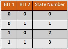
A bit is the smallest information that a computer can store. It is a single on/off state. So 1-bit can have two different possible states; 1 and 0. But let’s look at a 2-bit system. 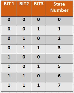
Since each bit can have two states, they can each be one or zero, so both together create 4 unique states (00, 01, 10, 11). So if we wanted to count to 3, we could use 2 bits to do it. It is important to remember that counting systems start at zero so they always count up to one number less than the number of states. If you were asked to count in binary to 4, you would have to include one more bit to do it (you would need 3 bits total). Let’s see how far we get with 3 bits. You can see something interesting from the table. We only added 1 bit but we have doubled the amount of states (we now have 8 unique states). In fact, every bit we add will double the total number of states.
|
|
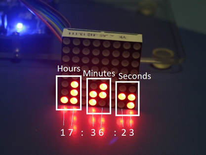
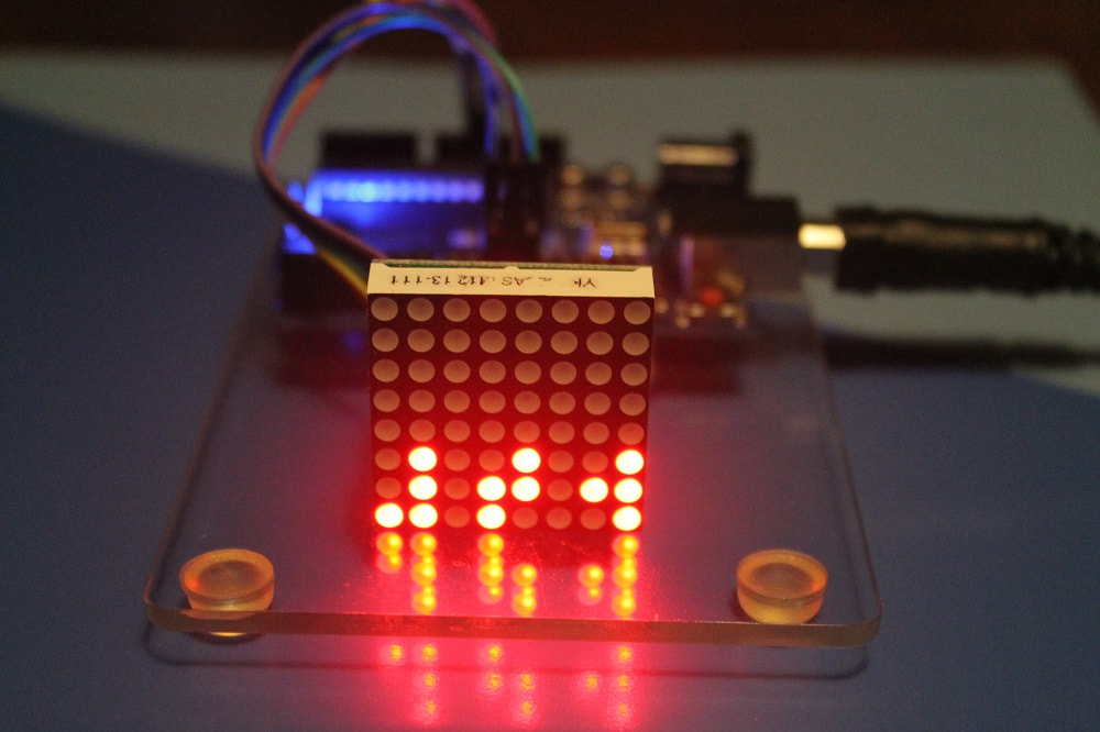
For our clock, we will use a system called Binary Coded Decimal (BCD). This is a method by which a decimal number is written so each digit is presented by a binary number. Since we need to represent 10 possible digits (0-9), we will need a binary number of 4 digits for each decimal digit. That actually counts from 0 to 15 (16 total digits), but we just won't use the binary numbers above 9 (1001 in binary). The LED matrix we will use is a readily available on eBay or at Banggood.com, Adafruit.com, or Sparkfun.com. It is an 8x8 LED matrix with a serial controller. You can get these very cheep as a kit if you have the means to put them together. We will use 3 sets of 8 LEDs to display the time (for the hour, minute, and seconds). Each LED is broken into 2 columns of 4 representing each decimal digit of the time. In the picture at left you can see this layout with the corresponding decimal number associated with its respective binary digit.
Click the file below to download the completed sketch
| binary_matrix_clock.ino |
The sketch was generated with very minimal code. Of note, to set the time, the time the sketch is compiled and uploaded is passed to the Arduino so the clock will automatically have the current time when it starts up. If you want to start with a specific time, you can just modify the setTime() parameters in the setup() routine. Make sure you have loaded the LedControl and Time libraries.
Do this in Sketch->Include Library->Manage Libraries, and then find the libraries in the list, click on them and then click the button on the lower right that says install.
Hook up the LED as follows:
+5V is connected to VCC
GND is connected to GND
pin 12 is connected to the DIN (or DatIn)
pin 11 is connected to the CLK
pin 10 is connected to CS (or LOAD)
Load the sketch and download to the Arduino. Then start working on your binary recognition.
If you like this clock, you should consider adding a couple of switches and the supporting code to be able to set the clock in run time.
