Estimate your local gravitational acceleration with Arduino
|
Gravity is a fact of life. And a good thing it is because it holds the Earth together, keeps us at a proper distance from the sun, and prevents our atmosphere from disappearing into space!
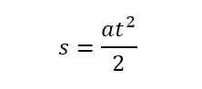
Gravity is a force that naturally exists as a function of mass. If you have a mass, it has a gravitational pull. It is an attractive force that pulls masses together. It is also very weak (relative to the other natural forces). Think about it. With every single atom of the Earth pulling you down, a simple pop of your leg muscles sends you in the opposite direction. The effect of gravity can be seen as objects fall to the Earth. Regardless of their mass, they fall at the same acceleration. This acceleration is roughly 9.8 meters per second squared (m/s²). We can actually measure this pretty closely (for experimental purposes) with an Arduino and some physics. Let's look at the physics. The distance an object falls (s) in a given amount of time (t) under constant acceleration (a) is given by the equation: |
|
If we rearrange the equation and solve for acceleration, we get:
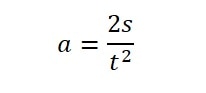
This means that if we know how long (t) and object takes to fall a certain distance (s), we can calculate the acceleration(a). Let's set up a lab that does just that.
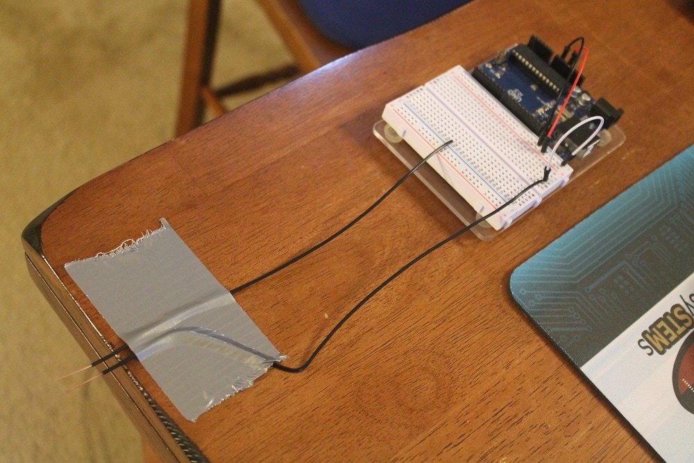
There are many ways to do this. What I am presenting here is a simple way with an Arduino and some household items. You can probably figure out some better ways with the stuff available to you so be inventive. The system we will setup will use and Arduino to measure the time it takes an object to fall a certain distance. We will use crude switches to let the Arduino know when to start and stop counting. Take a look at the parts we will use:
There are many ways to do this. What I am presenting here is a simple way with an Arduino and some household items. You can probably figure out some better ways with the stuff available to you so be inventive. The system we will setup will use and Arduino to measure the time it takes an object to fall a certain distance. We will use crude switches to let the Arduino know when to start and stop counting. Take a look at the parts we will use:
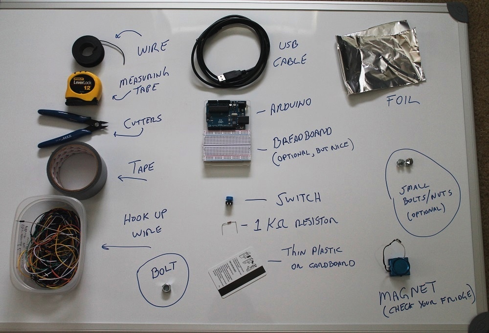
We will use bare wires, foil, and bolts to construct switches. We can locate 2 bare wire on a table top. We will use a bolt (or some other small metal object) to connect those wires together and a magnet to hold the bolt in place. With the bolt in place, the Arduino port will show a low, or ground, voltage which will be reported as a 0 in our code. When we remove the magnet, the bolt will fall and the wires will no longer be bridged. This will cause a high to be sensed on the Arduino port and will result in a logic 1 being reported to our code. We can use this transition from 0 to 1 on the port to start our timer.
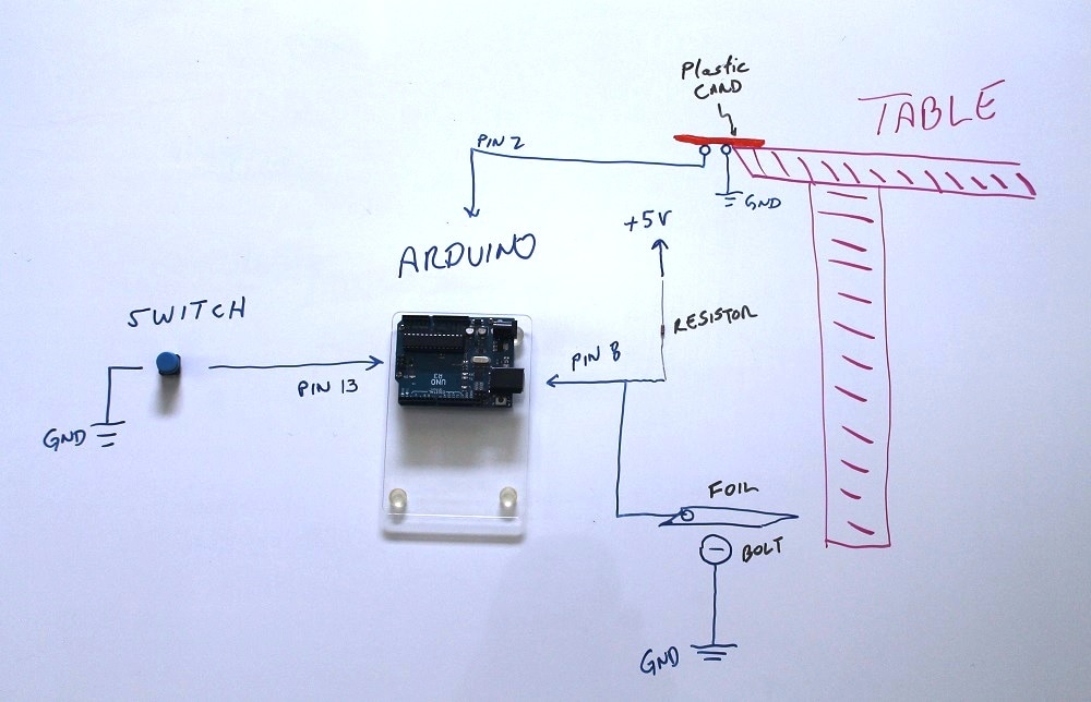
At the base target, we will do the opposite. We will have a bolt below, but not touching, a sheet of foil. We will connect the bolt to ground and the foil to our input on the Arduino. Without the foil touching the bolt, the port will register a high, or 1. When the falling bolt hits the foil it will make contact with the bolt and cause a low, or 0, to be seen on the port. We will use this 1 to 0 transition to stop the timer. This will give us the time it takes for the bolt to fall. If we measure the distance from the upper switch to the lower switch, we will have the distance it fell. That gives us everything we need to solve the above equation for acceleration. We will have the Arduino calculate this for us and report it via the Serial output. Let's set this up and see what happens. Below is a rough diagram of the setup.
At the base target, we will do the opposite. We will have a bolt below, but not touching, a sheet of foil. We will connect the bolt to ground and the foil to our input on the Arduino. Without the foil touching the bolt, the port will register a high, or 1. When the falling bolt hits the foil it will make contact with the bolt and cause a low, or 0, to be seen on the port. We will use this 1 to 0 transition to stop the timer. This will give us the time it takes for the bolt to fall. If we measure the distance from the upper switch to the lower switch, we will have the distance it fell. That gives us everything we need to solve the above equation for acceleration. We will have the Arduino calculate this for us and report it via the Serial output. Let's set this up and see what happens. Below is a rough diagram of the setup.
1. Build the upper sensor
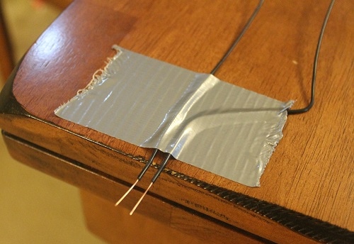
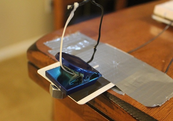
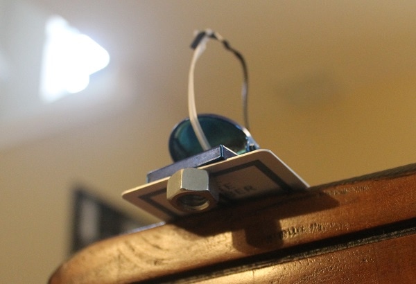
We will build the upper sensor with some bare wires, the plastic card, and some tape. Strip about an inch of insulation off of two wire. The length of the wire just needs to be long enough to reach your Arduino. If using a breadboard, run a wire from the ground (GND) and +5V supply on the Arduino to the breadboard for use by the added components. Tape the two wire to the table so they are close and parallel, but not touching. Connect one wire to ground and the other to Arduino digital port 2. See below.
|
|
Now, take the plastic or cardboard piece and tape it on top of the wires.
|

|
This will now allow you to place the bolt on the bottom of the card, bridging the 2 wires, and hold it in place with the magnet. Try it to ensure your magnet is strong enough to hold the bolt.
|
|
I put a couple of twist ties on my magnet to make it easier to lift off smoothly to release the bolt. Make sure your setup works smoothly. It should hold the bolt against the wires, and when the magnet is pulled away, the bolt should just fall with minimal disturbance of the system. Get another magnet, bolt, or plastic piece if needed to get this to work smoothly. Now we need to add our switch.
2. Add the switch
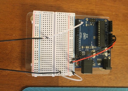
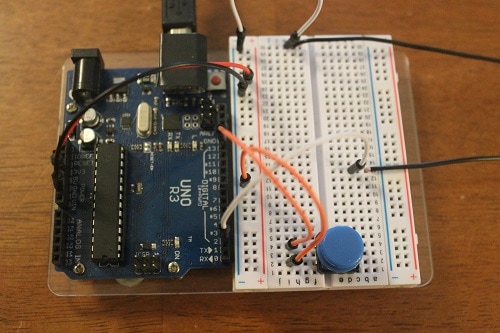
The switch you choose will determine how you hook it into the circuit. I am using a breadboard mountable switch so my connections will be easy. Place the switch in the breadboard and hook one side to ground and the other to the Arduino digital pin 13.
|
Pin 13 of the Arduino will normally be pulled high by the internal circuitry (actually, we are going to tell the Arduino to do this). This will appear as a 1 in the program. When we press the switch, it will connect the pin to ground and it will registered a 0. We will look for this as a reset signal for the system. Let's finish the hardware setup with construction of the ground collision sensor.
|
3. Bottom impact sensor
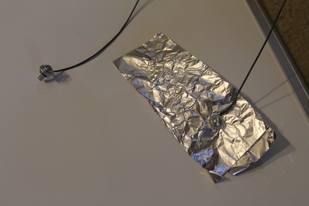
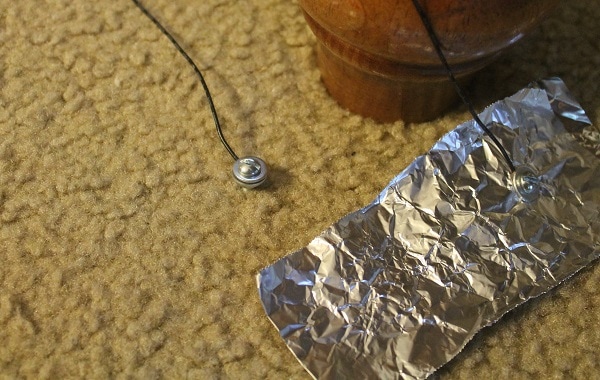
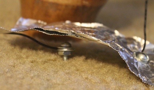
Now let's get to work on the lower sensor. This will detect when the bolt hits it. We will use a bolt and a piece of foil for this sensor. Cut two wires long enough to reach from the ground under the upper sensor to the Arduino. Strip some insulation off the end and attach it to the small bolt and to the foil. If you don't have bolts, you could use a big circle of bare wire as the base sensor and tape a wire to the foil.
Unlike the other two inputs where we will instruct the Arduino to pull the ports high, we are actually going to externally pull the lower sensor pin high. The internal pull-up resistors in the Arduino tend to be a relatively large value and noise from the long wire runs can cause false low readings. We will use a 1 kohm resistor to pull the pin high. Connect the 1 kohm resistor (color bands Brown/Black/Red) to the +5V and one of the bottom sensor wires. When done, it should look something like the following.
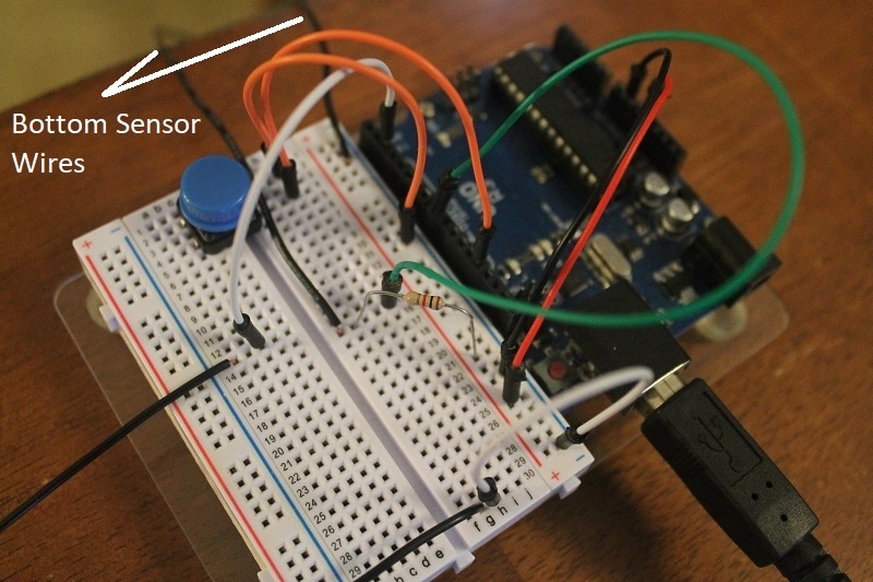
Finally, place the wire with the bolt on the ground directly below the falling bolt (you may need a couple of test drops to determine where this is). Then, place the foil so it is over the bolt but not touching it. See below for what this might look like.
|
|
That is it for the hardware setup. Now, let's write some code to bring this all together.
4. Arduino code
Now let's pull this all together with some code. Here is what we hope to accomplish with our program:
1. Initialize all of the inputs
2. Setup the Arduino to send text back to us via the serial monitor
3. Wait for the reset button to be pressed
4. Run a diagnostic to ensure the system is ready
5. Wait for the upper sensor to disconnect (the bolt has started it's fall). Start the timer.
6. Stop the timer when the bolt makes the bottom sensor connect (bolt has finished the fall).
7. Calculate and report the results
8. Goto step 3
You can click on the below link to download the sketch or just cut and paste it from below.
| gravity.ino |
Let's look at the code piece by piece to show how we accomplish the 8 steps above.
const int topSensor = 2; // Switch that detects start of fall
const int bottomSensor = 8; // Switch that detects end of fall
const int runReset = 13; // Switch that resets the system
const double distFall = 88.9; // Change this number to the number of centimeters between the upper and lower sensors
These lines allow us to set values to be used in the program. Rather than referring to port numbers, it is better to name the ports of the Arduino. This makes the code much more readable. We set up variables to represent the 3 input ports we will need. We also assign a value to the constant distFall. This is the only code that needs to be modified to run on your particular setup. Make sure that when you have completed your setup, that you use the measuring tape to measure the distance between the upper and lower sensors in centimeters. That value must be placed where the 88.9 value is located. That was the value for my setup but yours will be different.
void setup() {
// Since these are all switches, let's set them as Inputs with pullups
pinMode(topSensor, INPUT_PULLUP);
pinMode(bottomSensor, INPUT);
pinMode(runReset, INPUT_PULLUP);
Serial.begin(9600); // Start the serial port to output data
Serial.println("This sketch estimates the local gravitational acceleration");
Serial.println();
Serial.println("Setup the hardware and press reset when ready.");
Serial.println();
}
In the setup section of code, we set the pin modes of our inputs. Notice that for the switch and the upper sensor, we add the PULLUP modifier so the Arduino will enable the internal pullup resistor on those pins. On the lower sensor, we omit this because we pull up the signal externally for the reasons we discussed previously.
Next, we enable the Serial communication port and initialize it at a speed of 9600 baud. This will allow us to send text to the Serial monitor for us to communicate the status of the program, hardware, and the calculation results. We then print out a few lines of text to test the connection and introduce the program.
void loop() {
// Wait for reset button to be pressed
while (digitalRead(runReset)) {}
Serial.println("Reset...checking setup");
delay(500);
The loop() function is the place in an Arduino sketch that repeats over and over. That is good because step 8 was to go back and wait for the reset button to be pushed. So this is the code for the reset button. The while function does what is in the curly brackets as long as what ever is in the parentheses evaluates as true. Since our switch is normally 1, or true, until pressed, this "while" command will be satisfied until the switch is pushed. Since there is nothing in the curly brackets, it just waits until you press reset. When you do, the pin goes low, or false, the "while" condition is now false so the program jumps over the while command and starts with the next command to run. In this case it is a text output letting you know the sequence has started and the setup will be checked. So let's see how we check the setup.
// Reset was pressed, so check the setup
boolean flagSetup = true; // set this to false if there is a problem
Serial.print("Upper sensor is ");
Serial.println(digitalRead(topSensor));
if (digitalRead(topSensor)) flagSetup = false;
delay(1000);
Serial.print("Lower sensor is ");
Serial.println(digitalRead(bottomSensor));
if (!digitalRead(bottomSensor)) flagSetup = false;
The first thing we do is establish a boolean variable (flagSetup) to trigger false if we don't pass our tests. We initialize the variable to true and if a failure is detected, we will set it to false.
We then print the status of the upper sensor to the user.
We then test to see if the upper sensor is in the correct initial condition. This sensor starts with the two wires bridged by the large bolt which connects the port to ground. We test to see if this sensor is high instead of low and if it is, we set flagSetup to false.
We then delay a second and print out the status of the lower sensor to the user. Like before, we test the state of it. That sensor starts open and closes when the bolt hits it so we expect it to be high and not low. The if statement checks to see if it is low and if it is, sets the flagSetup to false. At the end of this code, flagSetup is true if we are good to proceed and false if there is a problem.
if (flagSetup) { // The setup is ok let's conduct the experiment
Serial.println("Ready!!");
// wait for the object to leave the upper sensor
while (!digitalRead(topSensor)) {}
// the object left the top sensor, capture the current time
double timeDrop = millis();
The if statement checks to see if we are good to run the experiment. If flagSetup is true, we start executing the test. We print "Ready" to the user and wait for the bolt to leave the upper sensor. The "while" statement is checking for the upper sensor wires to open and send a high to the pin. When it sees this, it fails it's condition and the next line creates a double precision variable and assigns it to the current value of the running clock. This is the start time of the drop. Now we need to wait for the bolt to trigger the bottom sensor.
// wait for the object to hit the bottom sensor
while (digitalRead(bottomSensor)) {}
// the object hit the bottom sensor, stop the time and calculate the acceleration
timeDrop = millis() - timeDrop;
double resultAcc = 20000 * distFall / (timeDrop * timeDrop);
The "while" function continually tests for the bolt to trigger the bottom sensor. When it does, the variable timeDrop is updated to the current value minus the original value. This is the time in milliseconds of the drop.
The final line establishes a double precision variable called resultAcc and assigns it to the calculated acceleration. This equation is the one stated at the beginning of this guide, but with the math worked out so the distance is in centimeters and the time is in milliseconds.
Serial.println();
Serial.println();
Serial.print("Calculated acceleration based on a fall time of ");
Serial.print(timeDrop);
Serial.println(" msec");
Serial.print("and a drop distance of ");
Serial.print(distFall);
Serial.println(" cm");
Serial.print("is ");
Serial.print(resultAcc);
Serial.println(" m/s^2");
Serial.println();
Serial.println();
Serial.println("Reset the hardware and press reset for another run.");
Serial.println();
} else { // There is a problem with the setup
Serial.println("Check your setup and press reset.");
Serial.println();
}
}
Serial.println();
Serial.print("Calculated acceleration based on a fall time of ");
Serial.print(timeDrop);
Serial.println(" msec");
Serial.print("and a drop distance of ");
Serial.print(distFall);
Serial.println(" cm");
Serial.print("is ");
Serial.print(resultAcc);
Serial.println(" m/s^2");
Serial.println();
Serial.println();
Serial.println("Reset the hardware and press reset for another run.");
Serial.println();
} else { // There is a problem with the setup
Serial.println("Check your setup and press reset.");
Serial.println();
}
}
Finally, we print out the test data to the user. We leave the user with a prompt to press reset. If this portion of the original "if" statement is being run, this will bypass the "else" statement and recycle back to the beginning of the loop() function.
If the original "if" statement failed, that means there is something wrong with the setup so we print that out to the user and recycle back up to start over.
Compile the sketch and download it to your Arduino. From the tools menu, start the Serial Monitor. You should see the startup text. Make sure your system hardware is reset (bolt is back up top held by the magnet and the lower sensor is positioned to detect the bolt when it hits). Press the reset button. Your Arduino will now check your setup. If all went well, it will tell you that you are Ready. Lift the magnet off the top sensor and let the bolt fall. When it hits the bottom, you should see the Arduino report the acceleration. Troubleshoot any problems and make adjustments as needed.
