Build a Switch Bounce Counter and See How Good Your Switches Really Are
We tend to think of switches as either on or off. However, mechanical switches are mechanical devices and as such, are susceptible to bouncing. Bouncing occurs when a switch changes position and proceeds to bounce off of (or momentarily lose contact with) its electrical contact. This has the effect of sending multiple, short duration pulses on the switch line before it settle on its new position. In a light switch, this is no big deal because these bounces are complete within such a short time that it is imperceptible. However, in digital circuits, this could look as if the switch is being cycled on and off dozens of times.
How bad is this problem? Let's conduct an experiment to find out.
How bad is this problem? Let's conduct an experiment to find out.
|
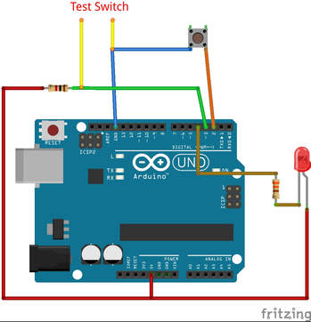
We will build our interface to include a switch to tell the software that we are ready to conduct a test and an LED to indicate when the computer is ready. We want to ensure we capture as many of the bounces as we can. However, these may happen extremely rapidly. Because of this, we will use and External Interrupt on the Arduino. An interrupt is a way that a computer is signaled to stop what it is doing and do something else. Think about the mouse on your computer. Since all software doesn't know when you will be moving your mouse, they would all need to have some sort of periodic checking to ensure they capture these movements. Instead, your mouse generates an interrupt to tell the system that it has moved. This way, all the movement is captured, and the software doesn't need to execute code that would mostly just be a waste of time since your mouse doesn't always move. By hooking our switch to one of the external interrupt pins on the Arduino (pin 3) we can set it up to count the number of transitions of the pin from HIGH to LOW and thus measure the number of bounces.
|
|
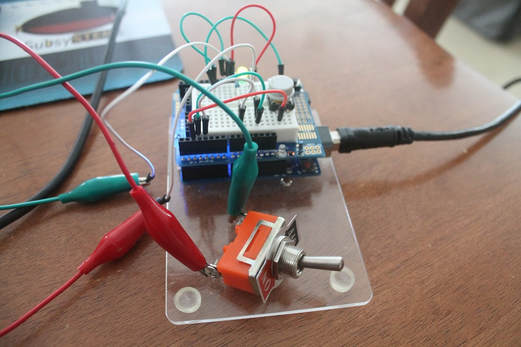
Lay the circuit out however you wish (I used a convenient breadboard proto shield). The switch will be used to tell the software to ready itself for a test run. The LED will signal that the computer is ready to start. And the test switch will be connected to the test connection. Make sure you have a reliable connection to the switch or you may induce a lot of noise (which will be recorded as bounces). Until I realized that my alligator clip on a screw terminal was loose, I was recording bounces in excess of 10,000!! Once I clipped the alligator clip to the terminal itself and not the screw, they began to show the actual bounce count.
Click the file below to download the completed sketch
| arduino_switchbounce.ino |
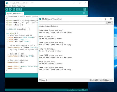
After initialization of the pinModes for the switches and the LED, the code starts the Serial port for output.
The code then waits for the START switch to be pressed.
Meanwhile, an interrupt service routine is waiting, always scanning pin 3 to look for the HIGH to LOW transitions. When the switch is thrown, the interrupt is generated and the counter is incremented each time the pin goes from a HIGH to LOW transisiton. After waiting 1 second after the first bounce is detected, the cumulative bounce count is reported over the Serial port to the Arduino Serial Monitor. The code then waits for the START button to be pressed to begin another run.
In digital circuits, this bouncing is compensated for with switch debouncing. This can be as simple as waiting a little while after a switch movement is detected before the program continues. This way the state of the switch is set before the program needs to accurately read it. This can also be done with hardware by using a multivibrator. This is a circuit that sends out a pulse of given size after it is triggered, ignoring any other input until the pulse time is up.
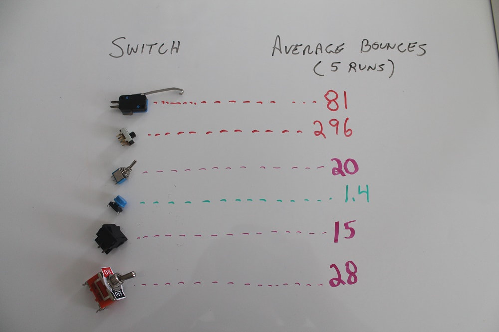
When I tested a few of the switches I had on hand, there was a variety of outcomes. Perhaps one of the more interesting results was that the slide switch had the worst bouncing. It seems counter-intuitive but actually makes sense when you look at how the slide switch works. When the slide is moved onto the contacting surface, there is an initial point of contact. In older (used) switches, this area begins to get damaged from the current arcing accros this point. Carbon builds up on the surface and reduces its conductivity. Over time, the whole mating surface becomes corroded and as the switch plate slides over the mating surface there are a lot of mating and demating events. The picture below shows some of the results of my tests. Have fun conducting your own, and remember, when coding, account for bounce!!
The code then waits for the START switch to be pressed.
Meanwhile, an interrupt service routine is waiting, always scanning pin 3 to look for the HIGH to LOW transitions. When the switch is thrown, the interrupt is generated and the counter is incremented each time the pin goes from a HIGH to LOW transisiton. After waiting 1 second after the first bounce is detected, the cumulative bounce count is reported over the Serial port to the Arduino Serial Monitor. The code then waits for the START button to be pressed to begin another run.
In digital circuits, this bouncing is compensated for with switch debouncing. This can be as simple as waiting a little while after a switch movement is detected before the program continues. This way the state of the switch is set before the program needs to accurately read it. This can also be done with hardware by using a multivibrator. This is a circuit that sends out a pulse of given size after it is triggered, ignoring any other input until the pulse time is up.
When I tested a few of the switches I had on hand, there was a variety of outcomes. Perhaps one of the more interesting results was that the slide switch had the worst bouncing. It seems counter-intuitive but actually makes sense when you look at how the slide switch works. When the slide is moved onto the contacting surface, there is an initial point of contact. In older (used) switches, this area begins to get damaged from the current arcing accros this point. Carbon builds up on the surface and reduces its conductivity. Over time, the whole mating surface becomes corroded and as the switch plate slides over the mating surface there are a lot of mating and demating events. The picture below shows some of the results of my tests. Have fun conducting your own, and remember, when coding, account for bounce!!
|
|
